
News information
News
The debugging of the foil winding machine is relatively simple, with less logical connections and fewer switching values. But for those who are not familiar with the equipment, it is still relatively unfamiliar. As on-site debugging is an appropriate and important link. Due to the dispersion of parts and the impact of installation processes, the installed products cannot meet the performance indicators required by the planning. It is necessary to test and adjust them to discover, correct, and make up for the functional and technical indicators specified in the technical documents, which is the debugging of the equipment. Together, debugging can uncover issues such as product planning, process, and raw material shortcomings and deficiencies. Therefore, debugging work is an important process to ensure and complete the functionality and quality of the product, which largely determines the quality of the entire machine. Some problems and shortcomings in equipment installation will be reflected through debugging.
It is essential to have a correct understanding of the effectiveness of each organization of the foil winding machine. Below is an introduction to the effectiveness of each organization and the common problems encountered. The foil winding machine (from front to back) consists of eight parts: operation panel, welding organization, deviation correction organization, winding organization, crimping organization, layer winding organization, uncoiling organization, and distribution cabinet. The first step in delivering equipment to the customer is to lift, place, and install the equipment. During the lifting process, most debugging personnel are present and should provide guidance on on-site lifting. Customers who are not familiar with the equipment may experience difficulty in lifting or damage to equipment components. Each equipment has an approximate weight, and any rope lifting equipment that exceeds the additional load must ensure the safety of personnel and equipment. According to the customer's requirements, the equipment should be placed in place, ensuring that the distance between the distribution cabinet and the equipment outlet is not too far (1m is appropriate). In the future, the on-site mechanical installation and electrical installation should be checked and acknowledged, and wiring can only be carried out after there is no error. As the factory disconnection and installation debugging may not be carried out by the same person, it is necessary to disconnect according to the drawings when disconnecting, and the different wire numbers should be marked and replaced, Ensure commonality with electrical drawings to prevent unnecessary trouble for installation personnel.
The on-site wiring is strictly carried out according to the drawings. If any mistakes are found, the local authorities should carefully consider the root cause. If the drawings and practices are not consistent, it is necessary to mark them carefully and investigate the operation phenomenon. The on-site wiring should be clear, concise, and not just focus on the results regardless of the process. The messy wiring will bring trouble to the protection and repair of future equipment.
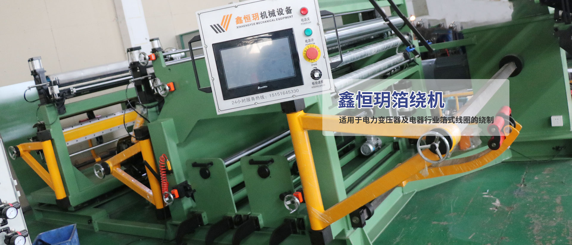
(1) The operation panel is a platform for human-machine communication, and all instructions must be given through the panel. Before powering on, check the three-phase communication voltage to prevent motor vibration or burning due to phase loss (under normal conditions, if there is a frequency converter, it will actively alarm for phase loss). After ensuring that there are no errors, press the start button to check the device's power on, including checking whether each action is reversed or not, and whether each button has output instructions; If there is no output based on the drawing, check the input and output points of the PLC (Chinese name: programmable logic controller, replacing the traditional relay contactor control system, making electrical repair more simple) and the module (referring to the extended input and output points of the PLC, the effect of the module adds the input and output points of the PLC host to meet the electrical equipment with more input and output points), and the corresponding green light on the PLC illuminates to indicate that there is input or output; If there is input but no output, check whether the air pressure button is open. Only when all buttons allow the air pressure button to be open can there be output. Confirm that the air pressure button is open. If there is input but no output, it is fundamentally determined that the module or program is responsible; If there are inputs and outputs, there is no action and output indication. It indicates that the 24V voltage output by the PLC has no effect on the relay or the relay has no action; (If there is any action, investigate the green light indicator on the corresponding relay, which illuminates to indicate that the relay is acting), and if the contactor is not acting (investigate whether the contactor is engaged), measure whether the contactor output is energized; If there is electricity, it can be determined that the cable from the contactor to the load fingertip is open circuit. Check the power line.
After the output of the frequency converter, for example, if the uncoiling motor does not operate, the first step is to determine whether the PLC has an output. If the button has an output indication, it indicates that the PLC has an output (both can be seen through the indicator light on the PLC). Then, investigate whether the frequency converter has any response. After switching the "" shift key, switch the display screen to the indicator light marked "Hz" below (the indicator light below A is on for current units, and the indicator light below V is on for voltage units), At this moment, the frequency of the frequency converter is displayed, and the flashing status indicates that the frequency converter is in standby mode, while the long light is in operation mode. Also investigate whether alarm indications and frequency converters display alarms, and use the alarm code table to determine what alarm is and how to solve it.
(2) The active welding structure is the primary equipment used before winding the coil. The organization is equipped with a specialized argon arc welding machine, and for the welding of foil materials, some operators may need to be trained because the different operation buttons of the welding machine may not be common. The training personnel need to understand the operation of the welding machine in advance in order to better train the operators. The welding of foil materials should meet the customer's requirements, The factors that affect the welding quality should be introduced to the operators one by one, including the details of the current (the thicker the data, the greater the current), the argon flow rate (the flow rate is too small to prevent oxidation and cooling, and the flow rate is too large to cause severe damage), the welding speed (the speed is too fast, the welding may not be firm, or it may not be able to be welded, and it is too slow to reduce), the welding gun angle (with flat welding), the welding interval Proficiency directly affects the quality of welding. Before welding, use a strong pliers to quickly align the copper (aluminum) row with the foil material (note: the row should be perpendicular to the end face of the foil material to avoid affecting regularity). Try not to leave any gaps (affecting the welding effect), and place it on the welding table, with an outstanding welding table of 3-5mm. Press the welding compression button (note: the downward pressure cylinder should not move too fast or slowly to prevent someone from accidentally pressing their fingers on the welding table). Release the strong pliers, Use a hammer to knock it all together. When welding, it is necessary to ensure that the cooling water pump of the welding machine operates normally and the argon gas is supplied normally. Welding can be carried out at a distance if the welding head is properly connected. During welding, high-frequency electromagnetic fields, infrared radiation, and ozone can be generated. It is necessary for operators to wear protective helmets and other effective measures, and exhaust equipment should be installed at the work site to pay attention to ventilation. When welding is completed, the welding switch should be turned off in a timely manner to prevent welding to the welding station and causing damage to the welding station.
There are welding limit switches at the left and right ends of the active welding clamp arm, which are travel switches for welding lead screws and guide rails to prevent the sliding out of the slider and lead screw mother. If there is a sliding out of the slider and lead screw mother, it indicates that the limit switch is not pressed down, and perhaps the wire of the limit switch is in an open circuit condition.
(3) The deviation adjustment system is an important part of winding, and the regularity of the winding coil is an important parameter to measure the performance of the equipment. During training, it is necessary to have the operator personally make the winding, explain the use of the entire deviation adjustment system, and promptly answer the operator's questions. The application of bias adjustment can be roughly divided into the following parts.
1. Center reset. Before placing the foil, place the bias control panel in the center (ensuring that the distance between the left and right movements of the foil is equal during the bias adjustment process).
2. Mold positioning. Before starting the winding process, the left end of the foil (the end of the spindle reducer) should be positioned first (depending on the customer's production requirements). After determining the orientation, measure the vertical spacing between the left end of the foil and the planes of each axis support, and set it as a
3. Place foil. The interval between the inner edge of the foil and the support plane should also be adjusted to a (this interval is approximately the number that the electric eye will actively adjust to a during the winding process)
4. Electric eye positioning. Pull the foil to the main axis winding direction, with the left end of the foil passing through the center of the electric eye. Measure the distance between the left end of the foil and the plane of the bracket as a (at this point, a should be as accurate as possible). When adjusting the orientation of the electric eye to light up one red and two green in sequence, lock the electric eye tightly.
5. Adjust sensitivity and balance. The deviation adjustment control panel has a row of indicator lights, which are adjusted according to the number of indicator lights on. Assuming that the center red light and the right two green lights are on at this moment, scroll the balance knob to the left until the center red light is on. Then turn the sensitivity button to the right about one grid, and if the panel shows one red in the center and two green in the right, continue to turn the balance button to the left. Based on past experience, adjusting the sensitivity button to the second to last grid (or less than the second grid) will cause device vibration. At this point, it is clarified that the sensitivity is too high, and the sensitivity should be reduced until there is no vibration direction. The cutting panel may have a red light in the center, or a red light in the center plus two green lights on both sides flashing. At this point, the deviation adjustment reaches the desired state.
6. Accurately adjust the orientation of the electric eye. In the first four steps, make sure to wind the device around 6 turns in the future (the device will actively align), investigate the deviation between the left edge of the active alignment and the positioning. If the orientation of the active alignment is 5mm to the right, reduce the spacing between the electric eye and the left end bracket plane by 5mm, and return the foil to start winding from the beginning. At this moment, you can actively adjust the correct orientation of the foil through the electric eye from the first lap onwards. The conditioning of insulation paper (DMD) is similar, and this adjustment is manual, which is simpler than the conditioning of foil and will not be explained in detail. The regularity of the purchased DMD determines the regularity of the DMD in the wire package.
There are several reasons that affect the improper winding of the foil material: the starting point orientation is not the same as the electric eye orientation, the foil itself has S-bends, the thickness of the mold is uneven, and the welding is not vertical, resulting in initial deviation.
(4) The winding organization is the part of the equipment that winds the coil. It is a three-phase variable frequency motor that passes through a worm gear reducer. It has advantages such as compact structure, large transmission ratio, low vibration, low noise, low energy consumption, and self-locking function under certain conditions. Dual power winding has a more uniform force than single power winding, with symmetrical motors and reducers on both sides. The synchronization adopts encoder tracking pulse mode, which means stepping on the foot switch and preparing the right motor. It is in a waiting state before receiving the pulse signal. In the system settings, there is a right machine start and stop time (note: the right machine stop time must be greater than the deceleration time of the main (left) machine, otherwise the two may not be synchronized when stopping). Assuming that the right machine start time is 1 second, that is, after the foot switch is activated, the right machine waits for 1 second, The two are started together, and the right encoder signal will transmit the changed pulse in real time to the right encoder as the speed increases, and compare it with the right encoder pulse. This means that the right encoder always follows the left encoder rolling, and the response is that the two operate synchronously. There are several reasons for asynchronous issues:
1. The start and stop times in the system settings are not set correctly or both are set to 0.
2. The coupling between the encoder and the motor is loose or broken.
3. Check the cable between the PG card and the encoder where there is a disconnection in the encoder cable.
4. The PG card on the frequency converter is damaged and replaced with a new one.
5. The encoder cable is disturbed by external power lines and the encoder shield wire is not grounded.
6. After replacing the gearbox, the reduction ratio is not completely the same, and the electronic gear ratio is changed on the frequency converter.
(5) The burring organization is a device for removing burrs from the edges of foil. Through the cylinder driving the shaft to roll, the burring wheel is pressed down to achieve the purpose of removing burrs. The device is relatively simple but also presents issues. The main reason for not tightening is due to low air pressure or relative sliding at the connection of the cylinder shaft that is not locked. Additionally, the two wheels are not parallel to the optical axis, with one side touching the foil and the other side not touching the wheel. The main reason is that the two wheels are installed in parallel before leaving the factory, and may not be completely common. After adjustment, they can generally meet the usage requirements.
(6) The layer insulation organization is the place where the layer insulation is placed, and the deviation of the layer insulation is adjusted using a manual handwheel (5mm per revolution). The starting position of the insulation paper placement is very important. The orientation of the insulation paper should be adjusted based on the orientation of the foil on the main shaft. There is a metal disk on the inflation shaft (the orientation can be adjusted and fixed according to the orientation of the insulation paper), and the insulation paper should be tightly attached to the disk. After positioning, the insulation paper should be inflated and locked tightly on the inflation shaft. An outstanding issue here is that the connection between the motor and the gearbox of the expansion shaft is not in a straight line, resulting in the motor running, excessive coupling noise, and high motor current. The faults of the layer receiving motor are identified through PLC and frequency converter like other motors, and adjusted to a better condition based on the parameters used by the layer receiving motor.
(7) Unwinding organization is a device for placing foil. During the winding process, the uncoiling motor supplies the foil with backward tension. The size of the tension can be given by the potentiometer on the operation panel (some of the input dimensions are given by the PLC analog quantity through the screen). When supplying tension, it is in the form of torque, while when unwinding and rewinding, it is in the form of speed. At this time, if the motor is stationary, it will not transfer to the overload alarm. The default speed for winding and unwinding is 8Hz. If it feels too slow or too fast, adjustments can be made appropriately. The left and right movement of the unwinding machine on the guide rail has the effect of adjusting the deviation, and the power comes from the deviation adjustment servo motor.
(8) The power distribution cabinet is the heart of the entire equipment. All signals need to pass through here before being transmitted to the execution section, and electrical repairs are primarily carried out here. Safety issues should be placed in an important position, and a distinction should be made between 380V power supply and 24V control supply. When repairing a circuit, it is necessary to cut off the power before operation, or perhaps use a visual test before operation. Exposed cables should be wrapped with insulating tape to avoid electric shock. The equipment body, distribution cabinet, and shielding wire should be grounded, as the rocker arm and the rotating part of the body are insulated. Therefore, the operating panel (with 220V communication power supply inside) should also be grounded with a grounding wire to ensure personal and equipment safety!